
This is the official website, of the Team SPACEY’s which refers to the Stratospheric Polarization Analysis for Calculating Electromagnetic Yaw. Our team is competing in the CAN-SBX(Canadian Stratospheric Balloon Experiment Design Challenge) competition, under SEDS Canada, as well as Canadian Space Agency.

The CAN-SBX is a competition for Canadian post-secondary students to design and test small scientific experiments that will fly on high-altitude balloons provided by the Canadian Space Agency. Students from Canadian universities and colleges can submit proposals, and the top teams will get to fully design, build, and fly their experiments. This year, they can use the new CSA balloon platform, allowing for payloads of up to 5 kg. The goal is to provide students with valuable experience in STEM and space exploration, and selected teams will be involved in launch operations, flight tracking, and payload recovery. The ultimate aim is to empower students to lead their own balloon launches in the future. You can find more information in the CAN-SBX Handbook linked below.https://seds.ca/can-sbx/
Primary Goal: Engineering
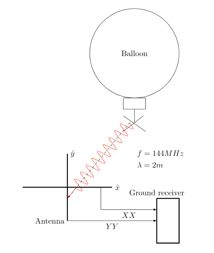
Our primary goal is to measure the physical rotation of the antenna on the antenna through the electric field observing from the ground station. Both the payload and the ground station are containing the antenna which primary we are considering two dipole antenna orthogonally placed. The more detailed system is as follows in the diagram on the left hand side.
The linearly polarized electromagnetic field will be emitted from each dipole antennas on the balloon at frequency range of 144 MHz.
Thanks to the dipole antenna’s radiation pattern which is shown in the below figure, where the radiation pattern shows electric field’s strong and weak point, and has the null point in the middle/feed point of the antenna. As the antenna rotates the observing antenna experience both maximum and minimum point of the radiation pattern, which coincides with the observing electric field strength. Since this null point/minimum radiation pattern along the antenna does not change, and purely due to geometry of the antenna, by measuring the period of the oscillatory behavior’s of the receiving signal strength it is possible to estimate the rotation speed of the antenna.
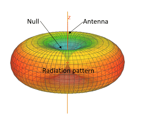
Dipole radiation pattern by: https://engibex.com/wp-content/uploads/2020/07/Radiation-pattern-of-a-dipole-antenna.-Antenna-is-oriented-vertically-along-Z-axis.png
In this experiment we are also encoding the gyroscopic data on the receiving signal through FM signal thus ultimately the receiving signal will be dual encoded in the AM for the rotation measurement, and acceleration/location measurement in FM.
Ultimately this experiment provides a method of obtaining the full state of the payload information in live manner with relatively smaller setup thanks so dual encoding system, and thanks to the rotation analyzation method requires no gyroscope on board thus creates more possibility for future research and application.
Experimental Equipment:
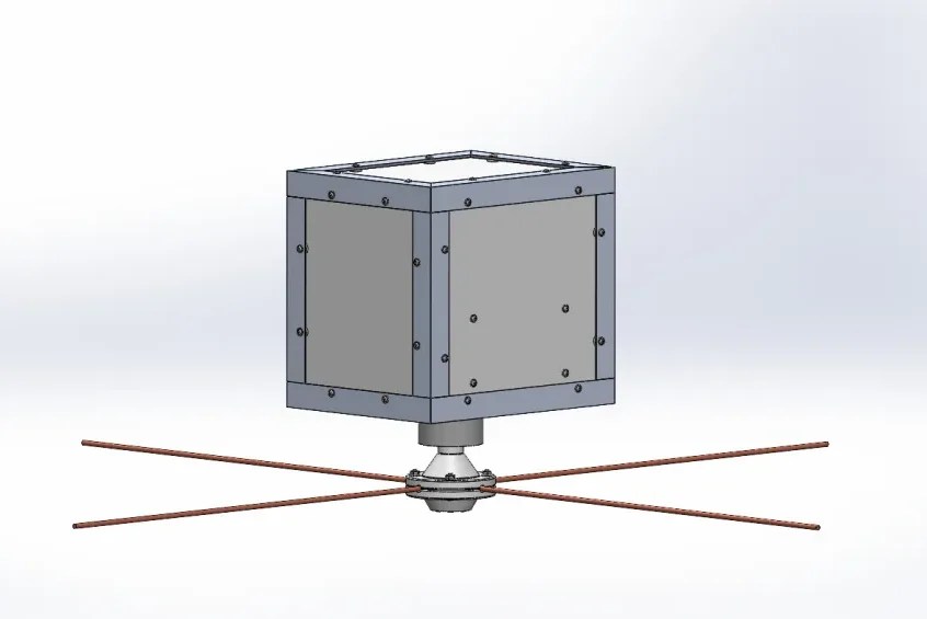
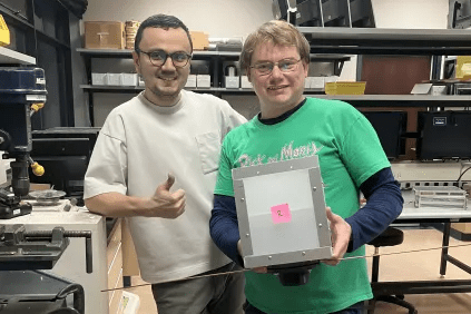
In the pictures below the first two pictures are the payload we have constructed which will host the experimental setups. The bottom of the payload has the protruding antenna which is mounted through mounting equipment that is constructed by the PLA using the 3D printer.
The picture bottom shows the electronics that we have for emitting the 144 MHz signal from the payload.

